TO ENABLE THE PHONE POWER TO 30W FOR THE CISCO EXPANSION MODULE PHONES
edit “phone-with-expansion-modules” set 802.3-tlvs power-negotiation end
config switch physical-port edit “port29” set cdp-status tx-rx set lldp-profile “phone-with-expansion-modules” set poe-port-priority critical-priority set speed auto next end
I know this is a strange requirement, but people out there if watching movies might need this when they share the movies through Media Player for streaming purpose.
We requires 2 paths to do this
A PowerShell script to rename file and a batch script to click and run this PowerShell Script -> to rename the filename
Foobar Software – a free opensource -> to rename the title of the file
The PowerShell script is as follows ( Copy Paste the below to your notepad and change the paramenters as required, Save the file as *.ps1 )
Make sure you put the above file to the directory where u want to change the filenames, You can add as many lines on the above Get-Childitem with replace command to replace the required filename strings as you desires
Now the Batch File to run the Powershell script, as you dont want to copy paste the Powershell script to the powershell everytime, so copy the below command (dont forget to change the filename of the powershell with the name of yours) to a notepad and save it as *.bat file
Create the Overlay Segment and attached to the overlay profile and click on SET DHCP CONFIG
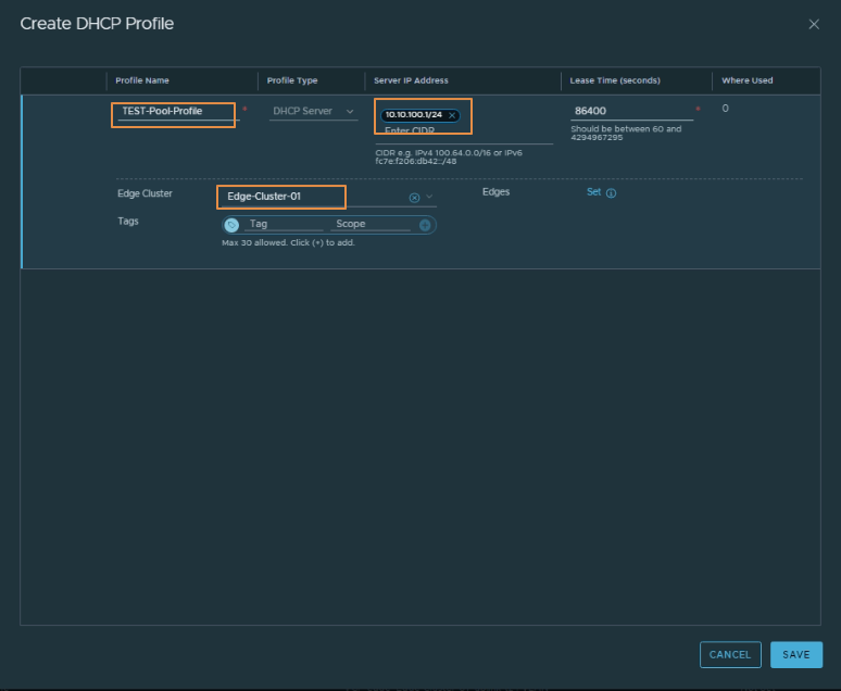
Now Select the LOCAL DHCP Server as DHCP Type and Click on DHCP Profile 3 dot buttons, for me the list shows the available profile, you will have create one profile to meet your Pool requirements
Input your required values as below and add to the Edge cluster
Input the values as below for the DHCP Server settings, Here as you can see you should set a different IP for the DHCP Server address in the same Network
while doing the above will configure the DHCP for the Segment
Have u received the below alert while installing the image or upgrading the F5, to see whether this logs is received
info: updating boot file /mnt/tm_install/24754.YRjazy/boot/vmlinuz error: copy /mnt/tm_install/24754.YRjazy/boot/vmlinuz failed; Permission denied Terminal error: Failed to install. *** Live install end at 2021/11/28 12:55:19: failed (return code 9)
check on “cat/var/log/liveinstall.log” after loggin in through CLI
to rectify the issue, simply delete the existing volumes under the software management completely and do the re-installation on the fresh partition.
i have came across this issue as i was trying to install the image on top of other image on the same partition, where a different version image was installed, so deleting the partition and creating the partition while installing the image resolved my issue
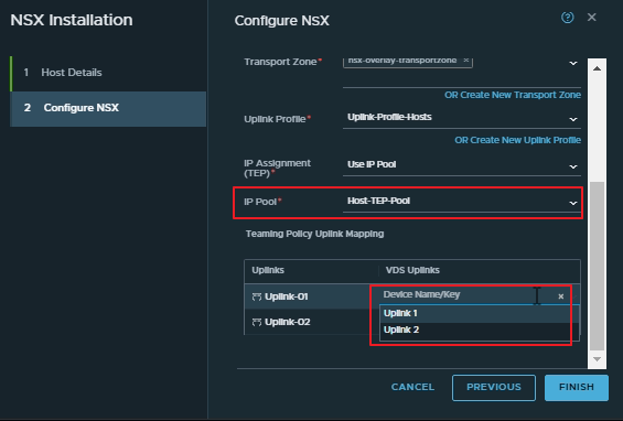
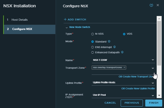
We have selected the VDS and it will automatically shows up the available Distributed switch, i have selected the distributed switch we have created for our purpose, and then we have selected only the overlay transport zone here, since it is directly connecting to the distributed switch there will be vlan port-groups available, so we dont have to select the vlan transport zone here, and only the overlay transport zone will do the purpose. After that i have selected the uplink profile and the IP pool for the TEP assignment
From the above screen we can see that it shows the available uplinks on the distribution switches, since we have mapped vmnic0 to uplink 1 and there is no redundant link available for my lab scenario, i will be selecting only uplink 1 and will leave uplink-02 blank as below
After clicking on FINISH i got the below error (which says the MTU requirements so let me change the MTU of the distributed switch)
To change the MTU settings we need to login to the VCenter and change that on the distributed switch propery as below
After changing the above value, i have applied the NSX-T configuration again and it proceeded
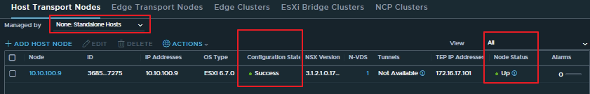
Wait for some time till the installation gets succeeded and the tunnel status to come up as below
Now lets check the Physical Host
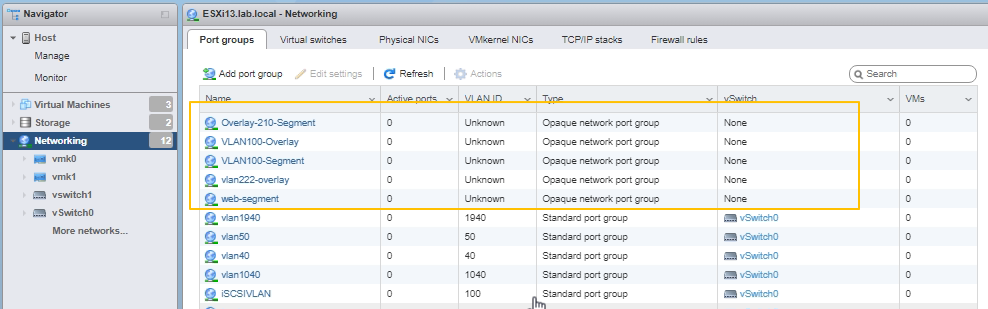
In the vcenter under the distribution switch we could see that all the segments got replicated and created here
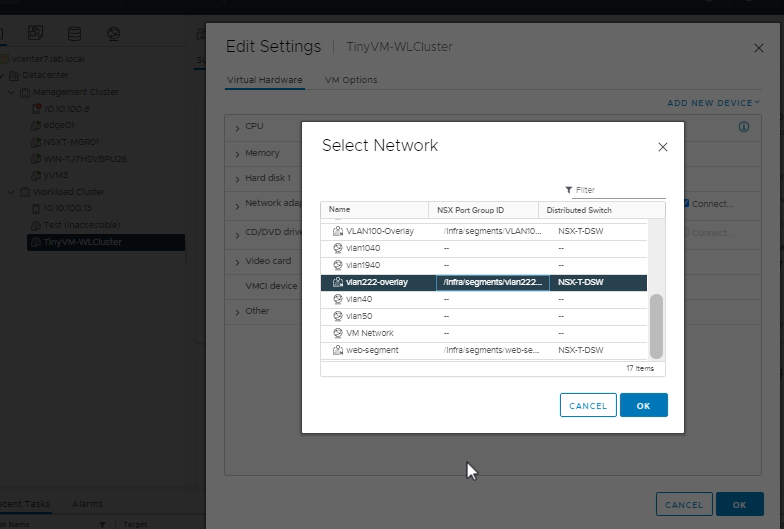
i will assign our one of the test VM to this vlan222 segment and once we select we can see on which Dist switch the segment is part of as below
After adding the VLAN also the device was not pinging, and i was researching the issue and i could see that the tunnel or TEP was not coming up between the host using the VDS method. Again i did some research and let me explain the issue in detail as below
As you can see that the Transport VLAN for the TEP communication is defined as VLAN90 and MTU as 1700, this VLAN90 was not configured under the distribution switch as a port-group, so i manually configured a port-group with VLAN90 under the distribution switch as below
The settings is as below its a simple vlan port-group
But after adding this also the tunnel didnt came up
After a few more research i got to find the issue, since the physical host is using nsxhostswitch we also required to create a VLAN segment for the VLAN90 in NSX-T so i created the VLAN segment as below
Now after doing this i made sure the vlan nsx-t port-group is visible on the ESXi Physical host
And also verified that this this vlan NSX-T segment is not appearing on the distributed switch of the vcenter as below
Why it is not appearing because we have selected the workload host to pass only overlay transport AND not the vlan transport
To get it clear see below
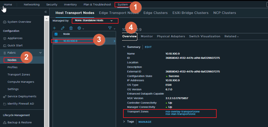
The below screenshot is for the physical host, where you can see both the overlay and vlan transport zone is selected
From the vcenter host we can see that we have selected only the overlay transport zone as below
And we can see that the tunnel is UP as below
and now the ping between the VMs on the workload cluster and the VM on the physical host is successfull
we have achieved our topology below and the testing is successful
Bonus Session
Lets test the MTU by using some Host cli commands
esxcli network ip interface ipv4 get
from the above command we can see the IP address of the tunnel interface which in our case is vmk10
esxcli network ip interface list
from this command we can see the mac address of the vmk10 which we can use to troubleshoot and see if it is learning on the correct transport TEP vlan or not
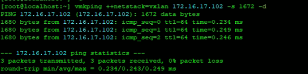
Now lets test the MTU using the below command
vmkping ++netstack=vxlan 172.16.17.102 -s 1673 -d
Since i have kept the MTU size as 1700 the max size i can use is 1672
This post is little lengthy but there is a lot to learn with the concept. Thanks for reading !!!
In the second design we are following the topology as below
wherein we will be using the distributed switch on one workload domain which is on vcenter and nsxhostswitch will be used on the physical ESXi and we will do the various test and deployments Support for VDS is included only on the latest version of NSX-T and not with the older versions
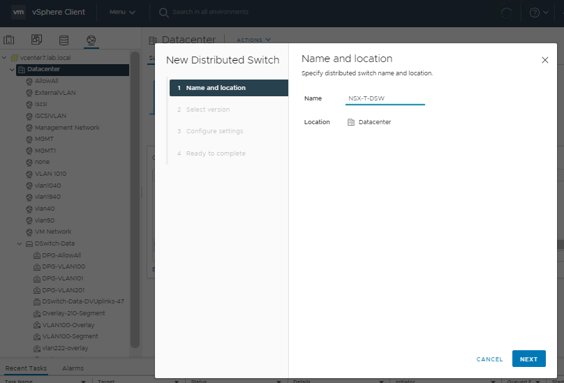
Lets create the Distributed switch first as in the screens below
The steps are self explanatory, what i’m doing is just creating the VDS
The below settings shows the distributed port-group settings which got created
And above you can see the uplink creation wherein all the VLANs are allowed by default
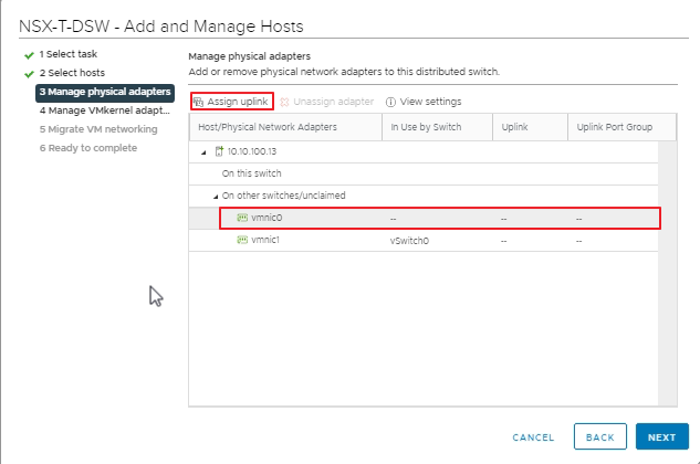
Now we need to map the interfaces with the distributed switch lets do that
So as per our topology we will map our host 10.10.100.13 vmnic0 to the distributed switch
To do that follow the below steps
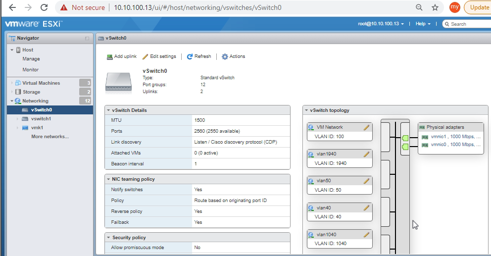
I dont want to loose the connectivity while doing the change so i checked where the vmkernel NICs are mapped and i could see that it is mapped with the vlan and vswitch0 and both the vmnic0 and vmnic1 is mapped to the same vswitch0 so i can remove vmnic0 from that vswitch safely without dropping the connection to the ESXISo as you can see below i have removed the vmnic0 from the vswitch0 and i will be using this for the distributed switch
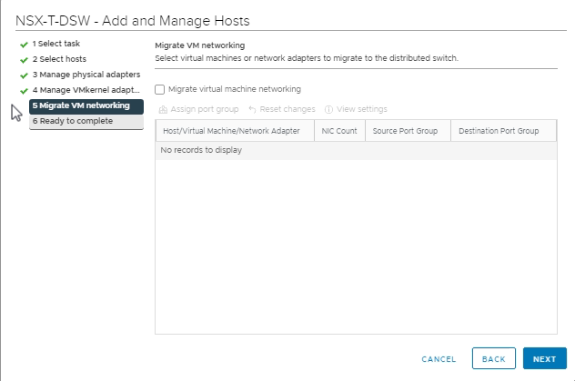
The below steps shows how to add the host to the distributed switch
So here am not assigning any VMKnics as it is already attached to the vmnic1 and the standard switch
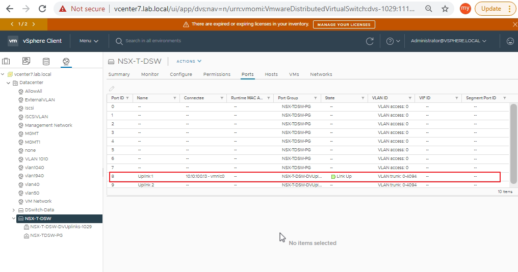
So we have completed the addition of this distribution switch to the host, so verified the same on the ESXi host as below
Same i can see on the vcenter as well
i dont want to make this session lengthy so i will go through the next post on the NSX-T with the distributed switch
I have added this session just to show how the uninstall works from our previous implementation where we have used vmnic’s as part of NSXHost Switch
But i want to add a bonus session here
change the Uplink profile from active/standby to loadbalnce
This is the current design where the vmnics are configured as active/standby
And Now lets change the uplink Profile
So created a loadbalance Profile as below
Now lets apply the load balance profile to the workload cluster
We changed to the Load Balance Profile as below
And Yes after applying the profile both the links are shown as active
So Now lets proceed with the uninstalling the NSX-T from the workload cluster Host
Click on Remove NSX as below
for me the same error appears as i was attaching a VM’s Network adapter with the NSX-T Transport Node VLAN (Overlay VLAN which we have created for the test VM), so i removed the Network adapter of the VM and tried again
And this time the delete works, it took a while for the uninstallation to complete
Now lets see what happens to our Vswitches and vmnics where it is getting associated in the ESXi Host lets see it
The VMK’s got assigned as per our configuration and this made sure that we did not loose connectivity to the ESXi Hosts after the uninstalling was performed
And we could see that vswitch0 has the 2 uplinks
So after we did the uninstalling the 2 uplinks got associated to the default vswitch0
There was no option as i see where we can configure that vmnic’s get associated to the correct vswitch as well, if someone has found a solution or better understanding on it please put in the comment box
Uninstalling NSX-T from a Host and adding the Host with the port-mapping and add the host when all the vmnics are used by the ESXi Hosts
Before proceding to the Next design topology lets uninstall the NSX-T and do an excecise of adding the host back to nsxhostswitch with the port mappings
Once you click remove NSX it will ask for Force delete check mark no need to click that you can proceed with the DELETE Button
I got the below alert
So removing the VM NIC from that interface and trying again (i moved that VM to a portgroup Network which is already available on the ESXi)
Now i can see its started its removal Job
So as you can see in the screen below it successfully removed
Now lets goto 10.10.100.13 and do a mapping of the VMNIC1 to some port-group and will do that Mapping while we configure the NSX while we add NSX-T to the ESXi and will try to do the uninstalling and see if that really works
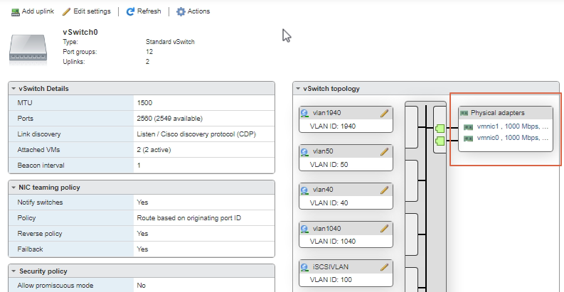
Step 1 : Adding the VMNIC1 to vSwitch0
Currently vswitch0 is tied with only vmnic0 lets add vmnic1 also to it this is one of the scenario which we face in the real time scenarios so lets work out with this solution
Click Actions Add Uplink and as you can see below Now it has 2 uplinks for the vswitch0 vmnic0 and vmnic1
Also from my VSwitch0 topology i can see that my vmk0 and vmk1 which are the kernal adapters and are important part of ESXi Management are also mapped to vswitch0, so now its upto us to decide how to migrate like whether we can keep it the same to vmnic0 as we are migrating only vmnic1 so all the kernal traffic will pass through vmnic0 or if you decide to migrate vmnic0 and vmnic1 also then this mapping is important
so lets add one more step here after migrating vmnic1 to the NSX-T lets migrate vmnic0 also to NSX-T by just modifying the uplink profile so lets that in action below
Step 2: Configure NSX-T, uplink profile and enable port only migration
All the below steps are same, so am just putting the sequence numbers to follow for you
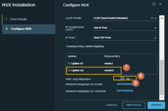
Now comes the important part make sure you give the correct name as matching the vmnic interface, in my case vmnic1
iam not using any migration of the vmks here but only the vmnic so enable the PNIC only Migration and click on FINISH it will start configuring NSX as below
After a while i could see the success status
In the vswitch0 of the ESXi host i could see that the vmnic1 is removed from the uplink of the vswitch0
while checking the portgroups i could see that all the NSX-T porgroup the 210 overlay segment all re-appears here
Another important point i have to say here in my recent screen you could see that node status was showing unknown and tunnel was not showing up, however now after i add the vm’s NIC to the overlay segment of the NSX-T our 210, node statud and the tunnel is showing up as below
Step 3: Move the vmnic0 also to NSX-T
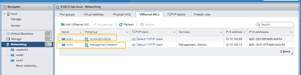
Before we move it lets capture and see the what is the portgroup of vmk’s, this is very important before we do the migration,
so we knows it is using 2 portgroups now lets see what VLAN is it mapped to
Ok so thats great eventhough the name is different it is mapped to VLAN100 so lets create a VLAN100 VLAN transport zone on the NSX-T
As you can see below we have it already created as part of the initial section in part-01 Link here
Now lets do the action,
Add the vmnic0 on uplink-02 as below, as said the name should exactly match as it is on ESXi Host also make sure that PNIC only migration is turned OFF here as we are also migrating the VMK’s here
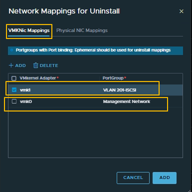
Once you click on the Network mappings for install make sure you map the details by matching the exact vmkernal adapter name and to the VLAN segment which we have created, you can press down arrow key and it will automatically appears there but vmk0 and vmk1 you have to type in with the exact names
Once you click Add and comes to the below screen you can see 2 Mappings available for the install and now click on the uninstall mapping as this is required while we uninstall the NSX-T then the vmnic and VM mappings has to return to there original state right
You have to be extra caution and type in the exact port-group values if you scroll up you can see that am using the same port-group values which was appearing on the vmkernal adapters, so i did a copy paste of the port-group values here
Now click on the physical NIC Mappings and click on Add button and the exact same names of the physical VMNics values here as below
AtleasT someone might think where we are mapping this uplinks to vswitch(s)while we do the uninstalling right ? hmm well a good doubt i too have it but better lets see those in action too
Click on ADD and now click on FINISH and lets see it in action
i was getting the bellow error message so let me power off the VMs and try it again, So one more lesson we need a downtime while we perform this task or migrate the VMs to another node in the cluster and perform the activity on one Node at a time, only point here is once you move or migrate back the vm the NIC adapter will be different on this Node it should be pointed to the NSX-T portgroup which we created i hope you got what am refering to here
I powered off the VMs and tried again and walla it was Smooth but with a partial success , and gives me the error as below and this error because the vmnic1 is active as per our uplink profile configuration where we have said one NIC to be active and a time and this can be seen from the switch visualization tab as below
So thats clear now only vmnic is active at a time and now there are 2 ways to resolve one change the uplink profile to make both NIC as active or change the order there as per the next screen below
this is what i was referring to so am just going through the different options
Change the teaming policy to load balance But make sure if you do that there are no Hosts tied with this policy at the moment
Change the active uplink to vmnic1 in the Configure NSX tab of Hosts this is the easiest solution here
So i changed the order of vmnic’s as below
And wallah
See the switch visualization tab and vmnic0 is the active uplink now
Lets see to our ESXi Host as well, and see there are no physical adapter tied to it
And the vmkernal port-group changed to unknown,
And there is no uplinks to any of the vswitches
Now if you want to do the uninstall it will be straightforward as we have did the proper port-mappings
Adding VCenter and VCenter Managed Workload Cluster or Hosts to NSX-T
For adding vcenter or the compute manager goto System -> Fabric -> Compute Manager
Adding vcenter is very straight forward as depicted below
After adding the vcenter Follow the below steps to add the Nodes
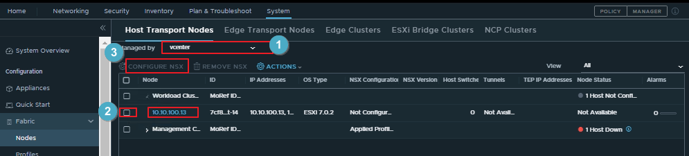
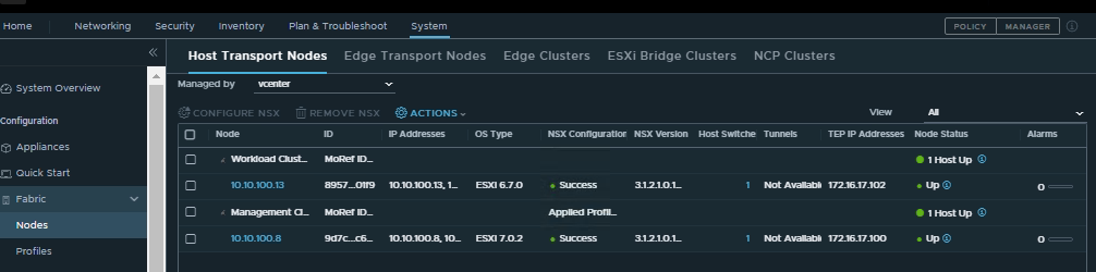
Goto System -> fabric -> Nodes
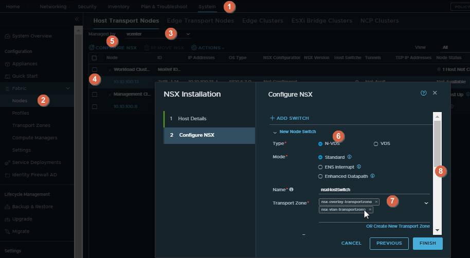
Then Select vcenter by using the drop down from Managed By, Also we can install or configure the same NSX Profile for the management cluster and workload cluster by selecting the multiple hosts or you can configure differente NSX Profiles for different hosts or nodes in each cluster, I am configuring different NSX profile for workload cluster and management cluster
Give the required details as below
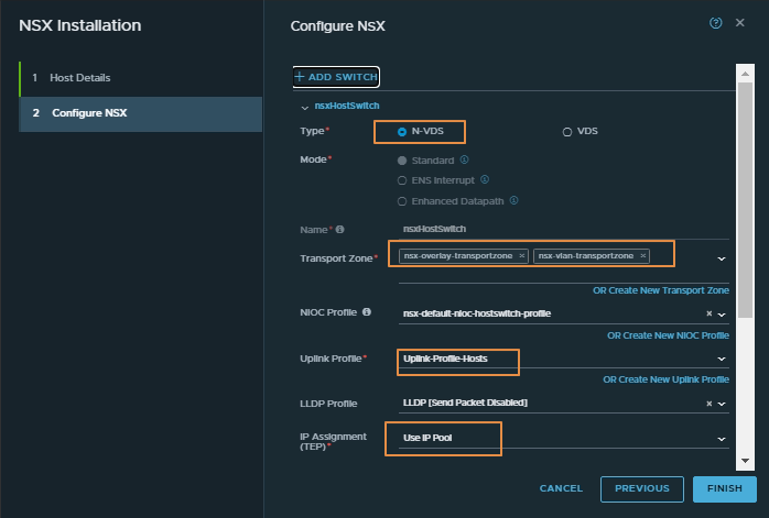
In the screenshot below we have selected N-VDS as our first test case for a workload cluster managed by VCenter
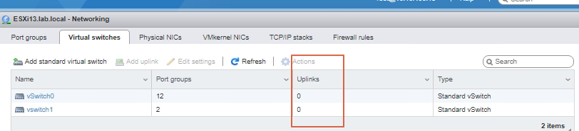
Please make sure about the point : iam using an unused vmnic here instead of using the existing NIC as you can see the ESXi below
USE CASE : By doing so we are not touching theirexisting production network and we can add the same production host to the NSX-T for any PoC Purpose(s). Consider if you dont have any free NICs, in that case we can try to make one NIC free and do the port-mapping as in the part-01 and can install NSX-T this way also we configure NSX-T in the production network (please note here that by doing so we will loose the redundancy on the host)
After waiting for a few mins you can see the NSX-T is configured and its up as below
Here if you noticed you can see 1 Tunnel is also showing Up lets see what it is, As you can see below it is the tunnel or TEP which is UP between this host and our physical host 10.10.100.9 which we did in the part01,
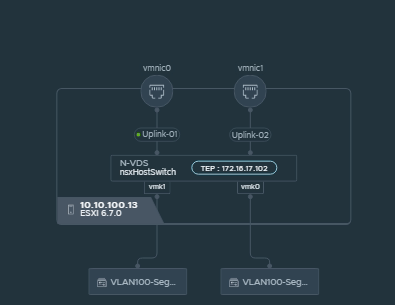
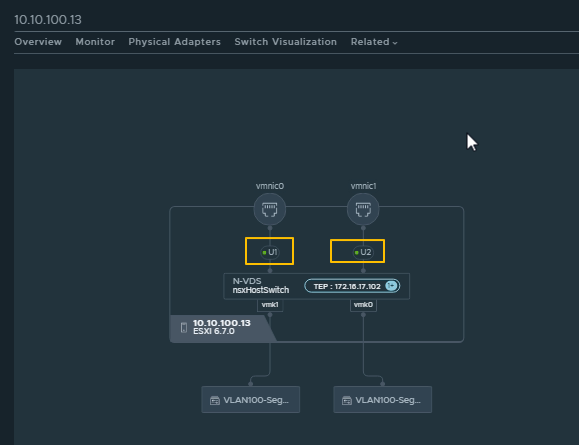
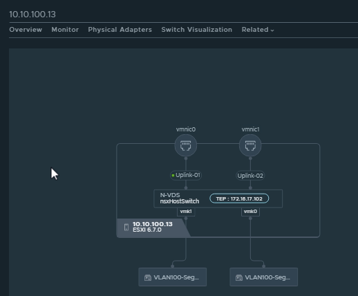
By Clicking on the switch visualization it will give a very nice view of the NSX-T configuration on the host as below
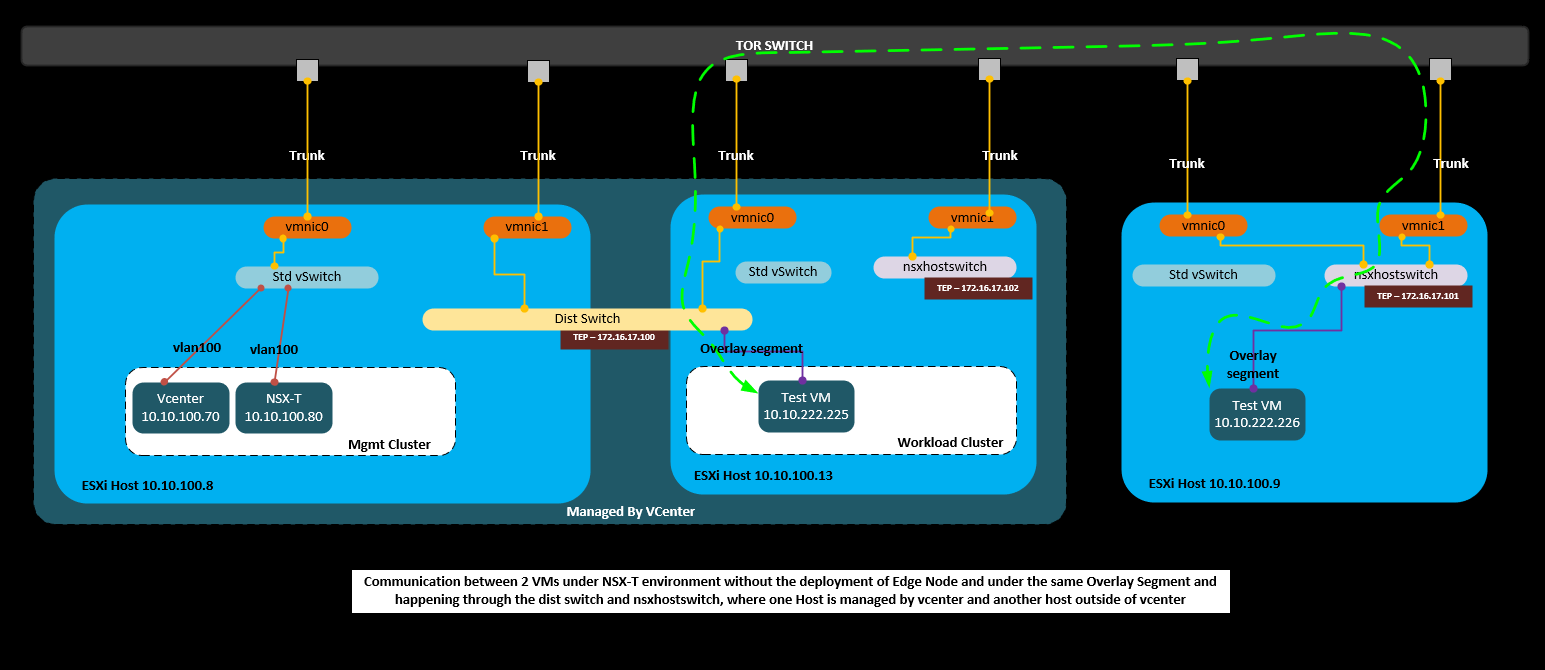
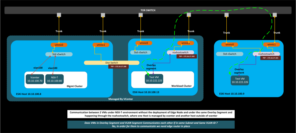
Below is the same topology to better illustrate it again to see what we are trying to achieve or what we have achieved till now, As you can see the TEP IP also on the figure below diagram and if you have given the TEP IP as static then you will be more sure about which host will be receiving that IP and so on, Since we have given as the IP POOL, i have to manually check and put it on the topology (and thats what SDDC is meant for, lessen the manual jobs 🙂 )
So as per the topology we have deployed NSX and now lets create one overlay segment and lets see if the overlay segment appears on both the host and the VMs can communicate each other through the overlay network
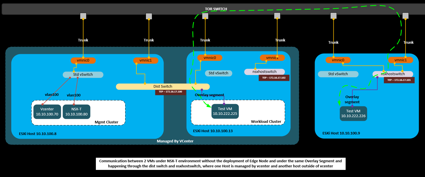
So the important point here is there is no edge routers and we are just creating an overlay segment and trying to see if the VM can communicate each other if its in the same segment and the VMs are in 2 different Hosts (one managed by vcenter cluster and another a physical host)
Creating the segment is far easier
Click No here and we are done with the segment creation and also you might have noticed that we have created the overlay transport zone here so we donot care about the undelying VLANS the communication between the VMs will happen through overlay
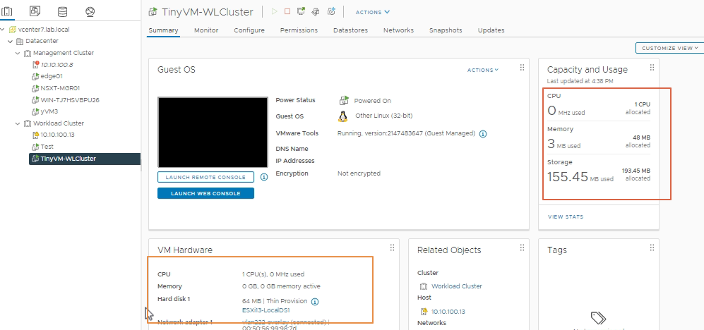
I am using TinyVM (you can find it on the Net) for my testing purpose as you can its a small size VM and i basically do only the ping tests
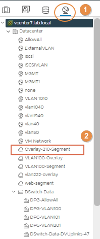
Lets see and add the newly created overlay segment 201 to the VM on the workload cluster and also to our VM on the Physical Host
On the vcenter this segment is appeared as below
If you are vmware expert this are very easy steps, below we have added the NIC card to the overlay segment 210 which we have created
we have assigned the IP Address to the tinyvm on workload cluster as below following our topology
So on the physical host also we can see that the overlay 210 segment is appearing as below
Also if you notice that the type is shown as opaque network port group as this is advertised from the NSX-T
we have added the NIC to the overlay segment as below
Assigned the IP Address as below
Now lets do the ping and seeAnd Yes we are able to reach the VM’s
Bonus Lesson
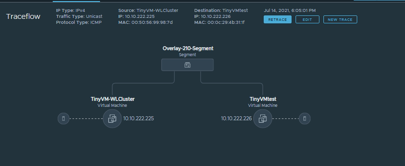
Now lets do the traceroute from NSX-T and see what path the VM takes
Goto Plan & Troubleshoot and traceflow and as you can see it will autofill the IP address details once you select the VM correctly
And BOOM it shows the complete visualized path how it takes if you want more deep just scroll down and more details as below
it even shows the TEP IP Address details while the packet traverses
With this we have achieved our first topology and test scenario Now lets proceed with the next topology in the next section
Today i thought to explain and lets learn together with the NSX-T journey. I was not a fan of NSX-V but from NSX-T 2.4 onwards i started to get more interest on it and with NSX-T 3.1 its really growing towards a stable and better SDDC Networking product
Coming from Networking background it is little tough to understand the vmware terminology and get proceed further with the NSX-T journey. So first we should need a better understanding of the vmware terminologies and vsphere concepts with the vm kernals, vmnics and all if you are an implementer of NSX-T solution, Otherwise if you are on an operational job, then you will not feel any difference from your networking world.
So Long story short – For a Network geek, little bit of vmware skill is required to start with the NSX-T implementation platform and that is purely my learning experience
In the below series i will start with the basic design and deployment scenarios which will cover some test cases as well, so we will have a better base on the deployment of the NSX-T
The above diagram shows the initial setup where the uplink TOR Switch is connected to 3 ESXi Hosts and one host in Workload cluster and one in management cluster and another one is a physical Host which is not managed by the VCenter
Importing of NSX-T Manager and Booting up is a simple process, Only to make sure that you point the NIC Adapter to the correct required Management VLAN, Provide the Static IP Address and the username/Password all the steps are self explanatory and i dont want to explain the steps again and again.
So considering the NSX-T is up and running lets do the Host Node addition
Adding a Physical Host to NSX-T
Lets add Physical ESXi Host to the NSX-T
There are some pre-requisites which has to be done before we add the Host Node to the NSX-T manager
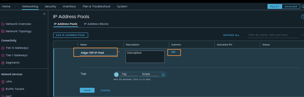
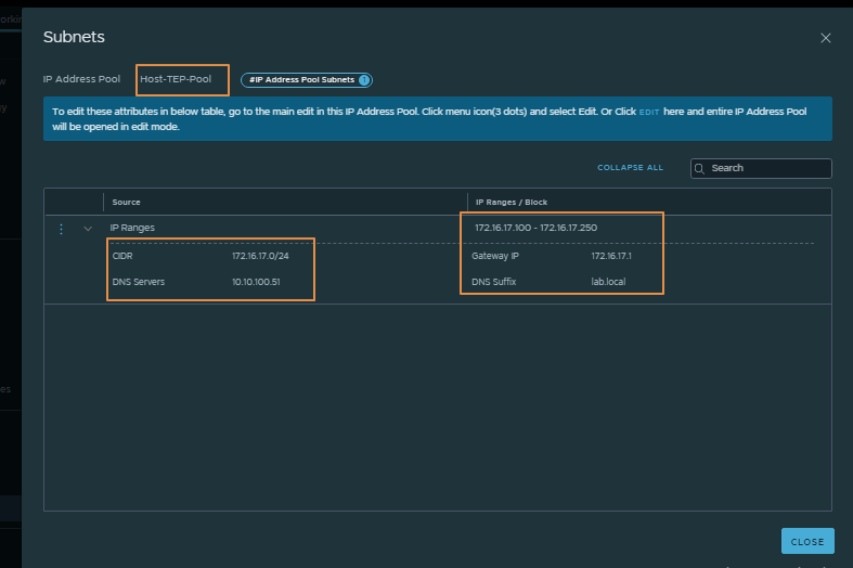
Create a Host TEP IP Pool and Edge TEP IP Pool
In the normal networking world we used to give Static IP Address to the Network Hops or Network Switches to manage independently, this Pool or TEP can be considered in the similar way and you can assign the IP address static or from the Pool or from the DHCP.
Lets create the Pool as per the VMWare standards
Goto Networking -> IP Management -> IP Address Pools
Please follow the sequence number and you are done creating the Pool, Please create the second IP Address Pool for the Edge Nodes as below
It is not mandatory to go forward with the IP Pools, we can also do the static IP Address pools while we create the Nodes and Edges
Now you can create an Uplink Profile or you can use the uplink profile which comes pre-defined with the NSX-T
For that Please goto System -> Fabric -> Profiles -> Uplink Profiles
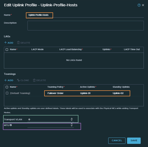
The above picture shows the Uplink profile which i have created for the Edge routers, here you can mention how many uplinks required, the best part of the profile is you can modify it in one single edit to all the edge routers, to show the same in coming steps, i have created only 1 Uplink here for the edge router, Another important thing to look at here is the MTU and transport VLAN , the transport VLAN i have used here is VLAN 90 and this is important as the transport VLAN set in the uplink profile tags overlay traffic only and the VLAN ID is used by the TEP endpoint. it can be put to the default VLAN value, in that case it will use the Native VLAN
To show the difference i have created the second Uplink Profile for the Hosts as below and here i have put the default values for the transport VLAN and MTU and added two uplinks for the teaming policy
Now lets add the physical Host to the NSX-T
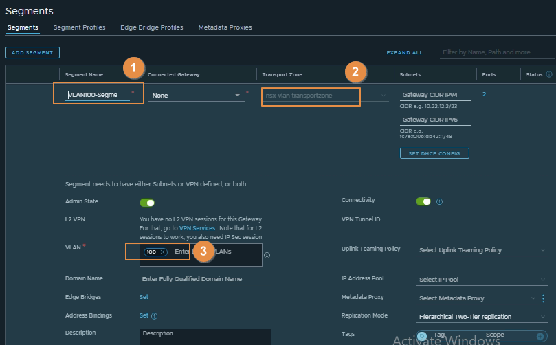
Before adding the host i will add VLAN 100 Segment as below
You will come to know why added the segment in this step after a while, this is used to migrate the VMNICs so that i dont lost the connectivity to the physical host while i migrate the ports to NSX-T, in 3 clicks the VLAN segment is created and its very straight forward
Goto Systems -> Fabric -> Nodes -> (Host Transport Node) -> Add Host Node
After Clicking on the Next it will ask to accept the thumbprint press Ok, so that a secure tunnel connection will be established between the host and NSX-T manager
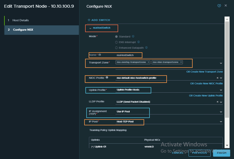
In the screenshot you can see that i have used the default transport zones and added both the vlan and overlay transport zone, and selected the uplink profile which we have created for the Hosts and based on the selected profile the NICs will be mapped and below you can see that the IP assignment option, i have selected the IP Pool you also have the option for the static and DHCP.
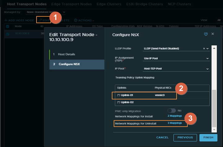
This is crucial part and you have to map the exact name of the physical NICs with the uplinks marked in orange
As you can see below the vmnic0 and vmnic1 is the same name as defined in the Host
(For the mapping marked as 2 mappings ) In the Network mapping where we have used the vlan 100 segment which we defined above to map the vmkernal adapters otherwise we will loose the connectivity
As you can see below the names of the vmkernal adapter should match exactly the same for the migration purpose Please note that i have captured the screen below after the migration steps is performed i.e why the portgroup is shown as unknown otherwise it will show the correct port-group and this is required to map the uninstall port mappings as in the next picture
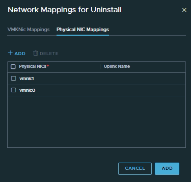
(For the mapping marked as 4 mappings ) this is used when we uninstall NSX-T from the physical hosts so that the actual mappings of the VMkernals and vmnics are mapped back (As said above the vmknics are mapped to the correct portgroup which is required while we do the uninstalling)
The below shows the physical NIC mappings you can put the uplink name in my case it was blank so i left it to default blank
Click FINISH and you are done, wait for a few minutes for the NSX-T to get configured and installed on the Host
Bonus Lesson
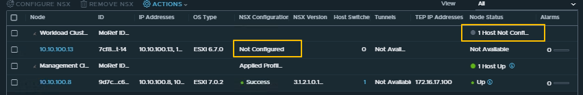
In my case it shows the Node status degraded and Alarms 1 lets see why it shows like this
Please note you may not have tunnels listed as you have only one host added, in my case i have another host also added as you can see my topology i.e. why the tunnel is showing as 1, you can ignore in your case for now
As you can see that one of the vmnic is down i.e the reason it was showing as down as i dont have the physical access to the DC now. lets make it as on one uplink to resolve the issue for now
You can edit the profiles anytime by clicking on the pencil icon and change the uplink profiles and those editable any time as below
As you can see the network mappings also removed the vmnic1 is mapping is removed from the uninstall part and also from the uplink profile mappingIn the part-02 i will show how to add the Vcenter and Vcenter managed workload and configure NSX